Safety in Numbers, Calculating Fall Clearance – Part 1
September 19, 2011
Maximizing safety and minimizing injury are the goals of any fall arrest system. But how do you know how much clearance is required for a system to be effective? Unfortunately there is not a concise answer to this question. Calculating fall clearance in order to choose the proper fall protection system for any application is a process that requires research and, many times, expertise.
When a worker falls on a fall arrest system, many variables come into play:
- What type of system are they attached to?
- Where are they tied off? Above the D-ring? Below the D-ring? (let’s hope not)
- Are there obstacles in their fall path?
- What is their harness made of?
While all these factors have to be considered, the fall arrest process can be broken down on paper, and as long as variables are recognized, an answer to your fall clearance questions can be found through basic measurements and calculations.
Simply put, fall clearance is defined as the height at which a worker must attach to an anchorage to avoid contact with a lower level. Before calculating fall clearance, it is important to define the various parts of the fall arrest process which will make up our fall clearance equation.
The parts of the fall arrest process…
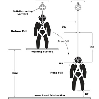
- Minimum Required Clearance (MRC) = Distance beneath the working surface to the nearest lower level obstruction.
- Total Fall Distance (TFD) = The total fall distance of the worker with equipment.
- Freefall Distance (FD) = The distance a person travels from the moment the fall occurs to the moment the fall arrest system is activated. OSHA regulations require that the freefall distance be 72″ or less. When used properly, Rigid Lifelines™ SRLs will activate within approximately 12″.
- Harness Stretch (HS) = The distance the harness stretches after forces have been absorbed by the harness thereby elongating the harness. Even a properly worn harness can stretch up to 12″ in length. Harness stretch is variable depending on elasticity of the harness webbing. Certain harnesses may be capable of stretching more than 12″.
- Deceleration Distance (DD) = The elongation of the deceleration device when deployed (e.g., rip stitch lanyard, self-retracting lanyard). ANSI Z359.1 states that a payout distance of no more than 42″ is required for this value. See manufacturer’s instructions for exact distances.
- Safety Factor (SF) = Additional fall clearance to ensure a safe distance from the obstruction after a fall. This variable number should take into account factors like D-ring movement. A distance of 18″ to 36″ should be included. The Safety Factor provides a buffer zone.
If you take all of these parts of the fall arrest process, you can assemble a fall clearance equation. Once put together, the equation looks like this:
FD + HS + DD + SF = TFD (Total Fall Distance)
and…
TFD (Total Fall Distance) must be less than MRC (Minimum Required Clearance)
All of these parts of the equation can be confusing, but let’s apply them to a real life fall arrest scenario and they should make sense.
Scenario 1

Calculating Fall Clearance Using a Rigid Lifelines™ Self-Retracting Lanyard (SRL)
In Scenario 1 we are showing a worker that is using a Rigid Lifelines™ SRL attached to a rigid overhead anchorage on an elevated working surface. In this scenario if the worker freefalls, the SRL should activate within 12″. Upon activation of the unit, the SRL will start to arrest the fall and decelerate the worker with its internal braking system. The employment of the brake should cause the lanyard to “pay out” no more than 30″ when the attachment point is directly overhead. At this point, any further fall distance will come from the stretch of the harness or movement of the D-ring. To calculate the Total Fall Distance in this scenario, the calculation would look like this:
FD (12″) + DD (30″*) + HS (12″) + SF (36″) = TFD (90″)
*Deceleration Distance of 30″ is a conservative estimate and excludes swing fall distance. If clearances are questionable consult a Qualified Person (as defined by OSHA).
The overall fall distance in Scenario 1 is 7.5 ft. This distance must be less than the measured distance from the bottom of the working surface to the nearest lower level or obstacle (MRC). If the fall distance is not less than the minimum required then a different fall arrest solution must be used.
In Scenario 2, a Shock-Absorbing Lanyard (SAL) is introduced. Rigid Lifelines™ does not recommend the use of SALs (sometimes also referred to as “rip stitch” lanyards) on overhead horizontal fall protection systems. These lanyards are frequently misused in applications with fall clearances under 18.5 ft and they can cause significant injury or harm to workers because of their potential elongation. Rigid Lifelines™ always recommends the use of self-retracting lanyards when possible because of their quick lock-up speed.
Please stop back next week to learn about calculating fall distance in Scenario 2 and remember to always check the manufacturer’s specifications for your equipment and inspect all equipment regularly to ensure that it is functioning properly and is free from signs of wear, damage, or fatigue.
Thanks for reading!
Michael Evanko
Marketing Manager
Side Note: If your application has a fall clearance less than 90″ contact Rigid Lifelines™ sales and engineering for an analysis of your specific application for an optimum fall arrest system solution.
Categories
Share this post
Let us help you
Contact us today to find the perfect product fit for your job
